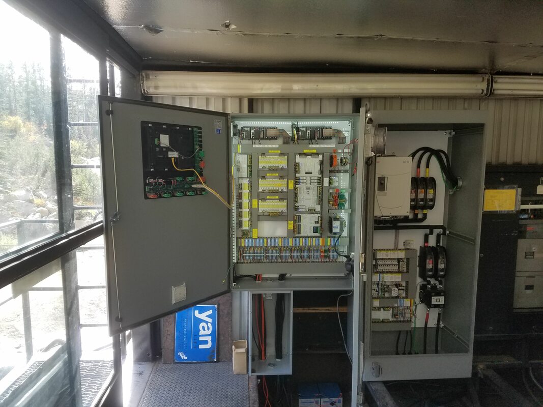
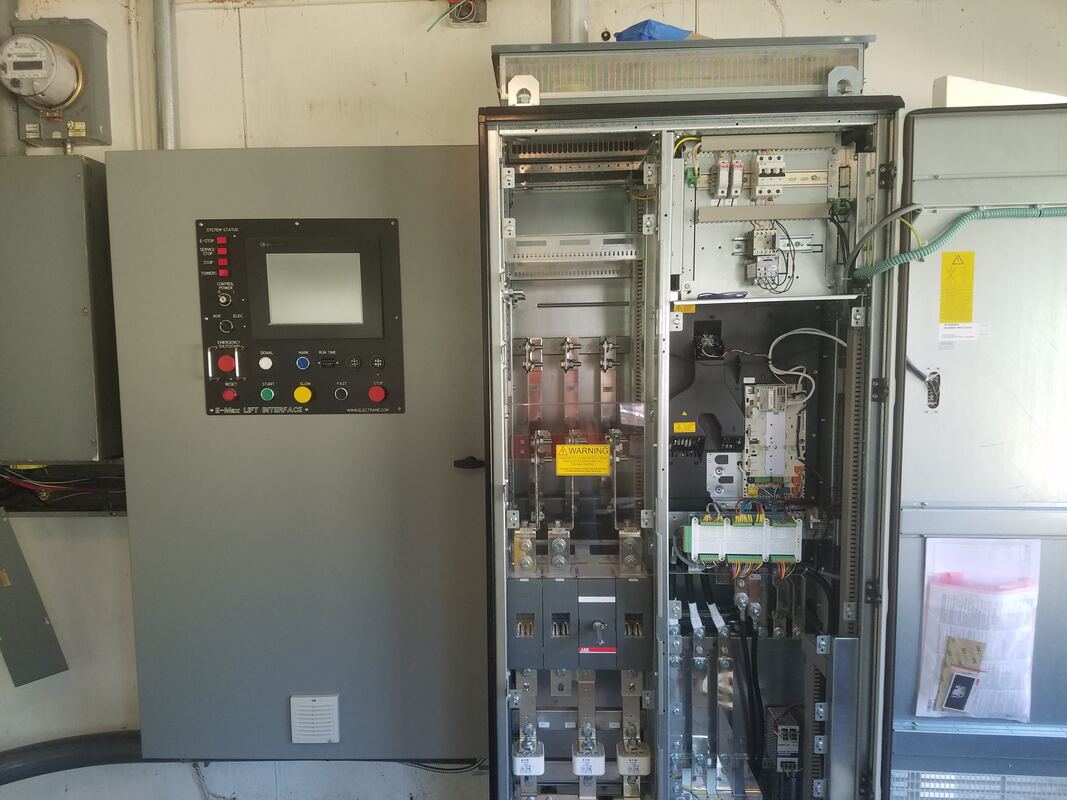
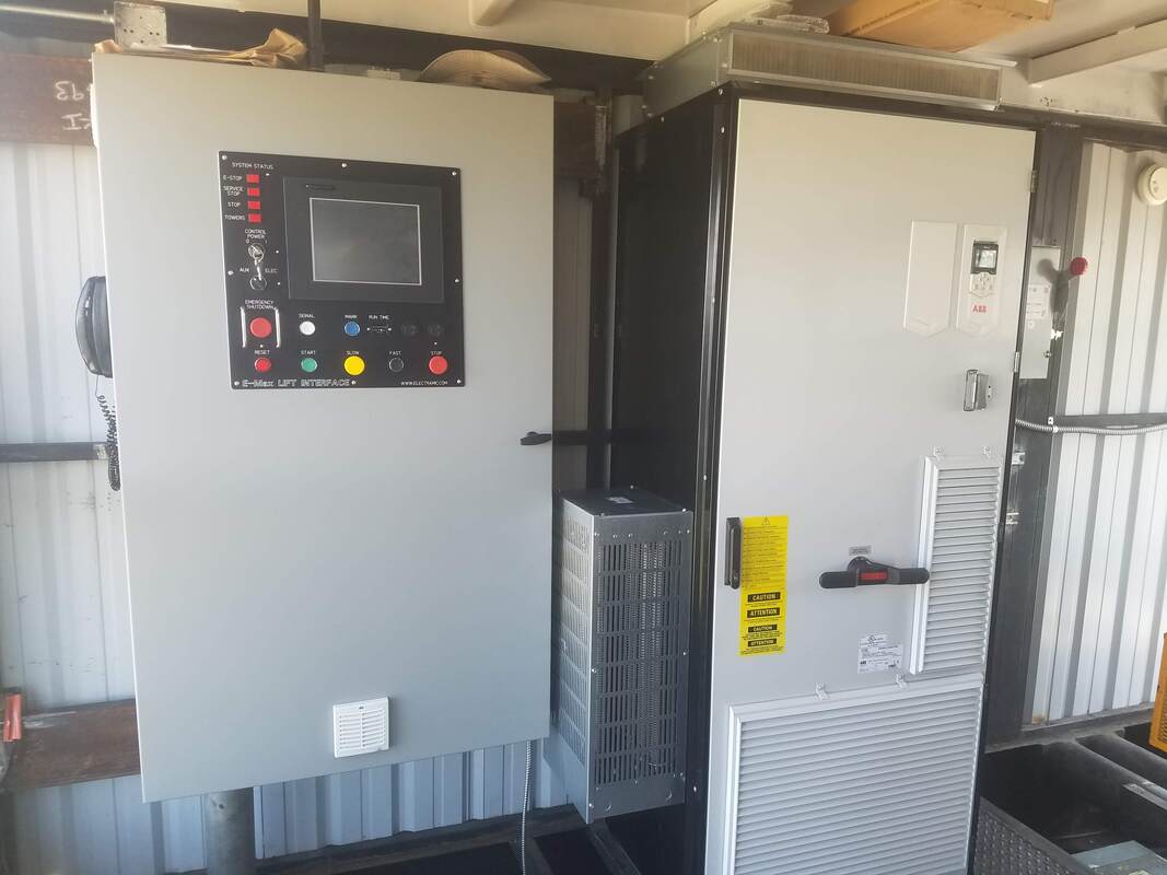
The E-Max system is modular in design, eliminating most of the wiring normally associated with modern control systems. All system connections are made via quick-disconnect terminals that incorporate spring-cage technology (no screws to loosen).
The system uses two Programmable Logic Controllers that simultaneously monitor all lift safety circuits, lift speed, and (as required by code) accel - decel ramp curves. Both the electric and auxiliary drives are constantly monitored for status, depending on which is currently being used.
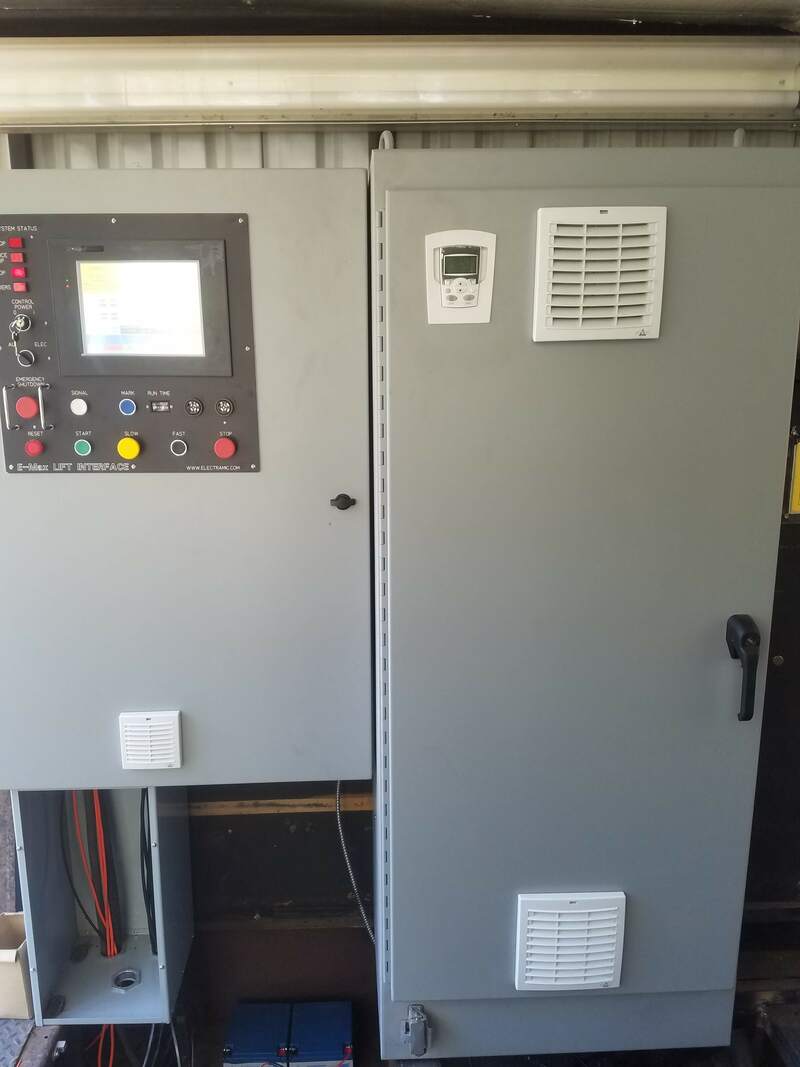
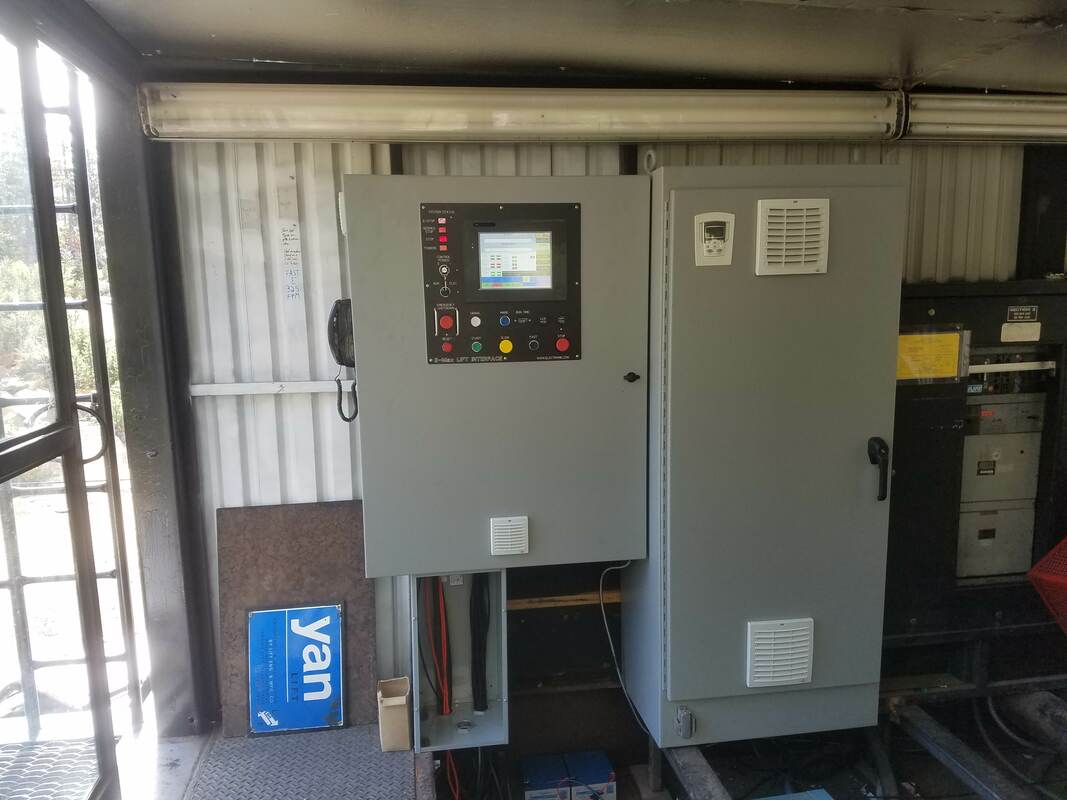
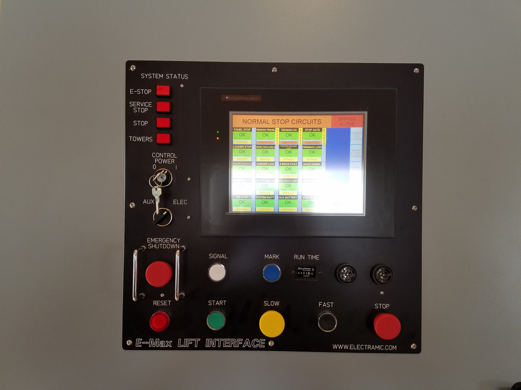
The primary operator interface is a 10.5 inch TFT color touch screen which (on the “home screen”) clearly and straightforwardly displays speed, load, and the current status of all lift subsystems. Alternate screens may be called up to aid in testing and troubleshooting. We do not use “fault codes” – just plain English. The status of all system inputs and outputs is also indicated with bi-color LEDs at the point of system entry or exit – thus backing up the touch screen and providing the technician with “cabinet open” system information.
Every system is custom built for your application.
Drive and System tests are available via the service screen and all test instructions are displayed in each test screen, eliminating need for written procedures.
Dynamic brake testing is fully automated: start the lift and push the brake test button. Motor current and speed are measured and the results displayed at the conclusion of the test. Daily tower circuit testing works in a similar manner.
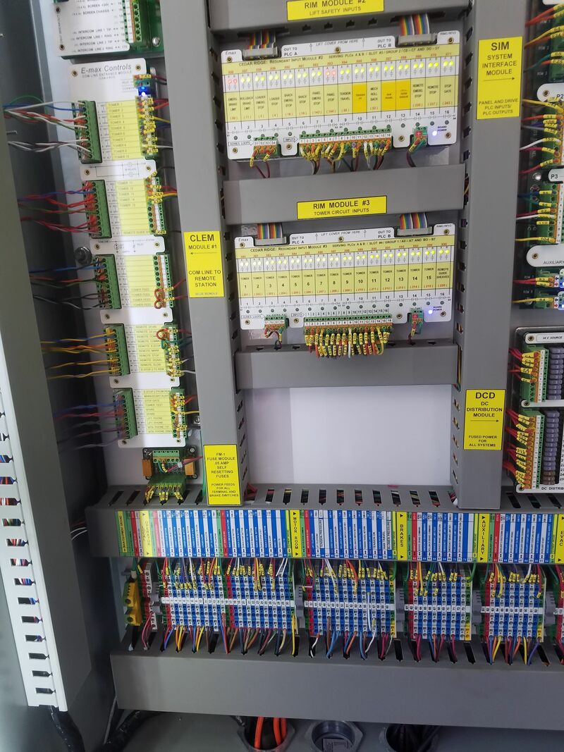
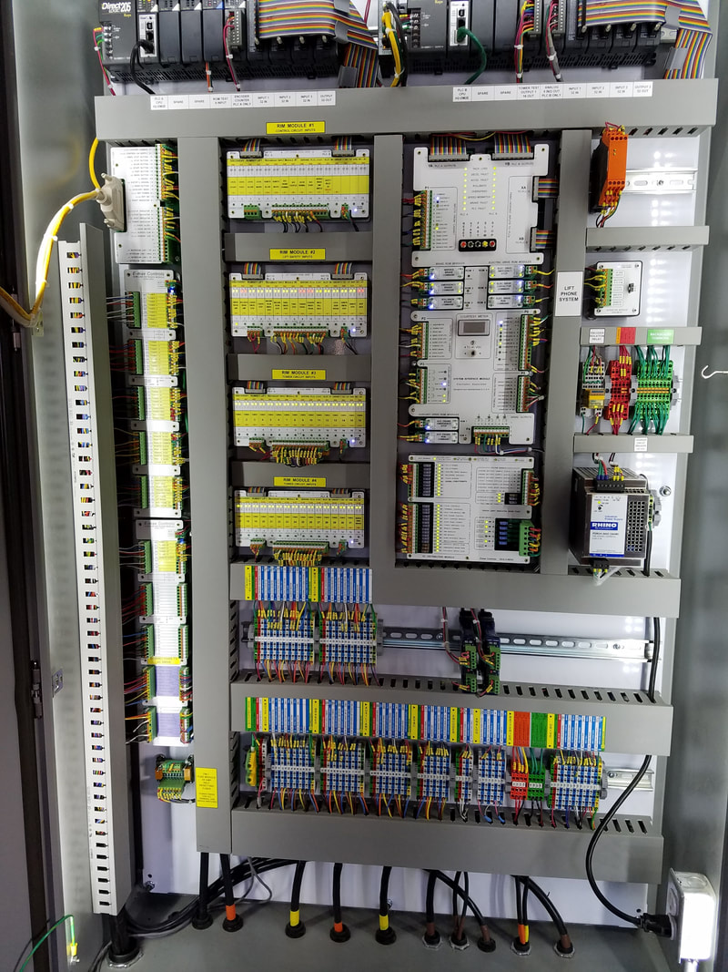
All external signals connect to input relay modules that split the signals, and connect via cables to both PLCs. Input relay modules have status led’s incorporated with a legend - customized to the user’s lift - for easy identification of all safety circuits.
A secondary “series loop” which includes all safety circuits is integrated into the relay input modules both as a back-up and to improve safety while operating in either of the EVAC modes (electric or combustion engine).
All PLC outputs connect to the system interface module (the SIM, as we call it). The SIM is an output relay module connected via cables to control drive, aux and brake operations. Both PLCs must agree to enable all safety-sensitive control outputs. The driven devices are monitored for correct response to issued commands.
A rope-driven optical encoder (tach) is constantly compared to a similar encoder on the electric motor. Together, they provide the system with speed, accel / decel and direction information. Disagreement of these two signals is regarded as a system fault.
A modular phone system is provided as the lift intercom. It uses a phone interface module and is supplied with polycarbonate handsets with armored cords. It is powered by the control battery.
A custom lightning suppression module is provided for com-line termination at both terminals. Wire connection on both sides of this module is via spring-cage, pluggable connectors. Within the “home” module, integrated entrance relays –responsive to system “on-off” - disconnect the system from the com-line and ground all com-line conductors to minimize induced voltages.
A 24 volt power supply and sealed batteries are included. Charger function and the voltage of all batteries is monitored by the PLC and displayed on the “home” touch screen. Distribution of 24 volt control power is centralized on a DC Distribution module. This module has input terminations for all possible system batteries: system; aux engine; brake (if separate); and evac supply. These inputs are appropriately switched and delivered to 28 individual ATM fuses that serve the various system loads. Each fuse is “green=OK” LED verified.
Tower circuits can accommodate any switch or configuration. Self-resetting Polyswitch fuses are provided for each tower circuit and are located at the return terminal. Tower wiring needs only 1 wire per tower + 2 pairs for power feed. An automated “tower test” function is standard.
A chair marking system sounds an alarm upon arrival of “marked” carrier at the opposite station. Start warning horns activate before the lift is moving.
Virtually any DC or AC drive integrates directly to the low voltage via a dedicated “electric drive” termination plug-strip. The auxiliary engine connects in similar manner.
The system uses two Programmable Logic Controllers that simultaneously monitor all lift safety circuits, lift speed, and (as required by code) accel - decel ramp curves. Both the electric and auxiliary drives are constantly monitored for status, depending on which is currently being used.
The primary operator interface is a 10.5 inch TFT color touch screen which (on the “home screen”) clearly and straightforwardly displays speed, load, and the current status of all lift subsystems. Alternate screens may be called up to aid in testing and troubleshooting. We do not use “fault codes” – just plain English. The status of all system inputs and outputs is also indicated with bi-color LEDs at the point of system entry or exit – thus backing up the touch screen and providing the technician with “cabinet open” system information.
Every system is custom built for your application.
Drive and System tests are available via the service screen and all test instructions are displayed in each test screen, eliminating need for written procedures.
Dynamic brake testing is fully automated: start the lift and push the brake test button. Motor current and speed are measured and the results displayed at the conclusion of the test. Daily tower circuit testing works in a similar manner.
All external signals connect to input relay modules that split the signals, and connect via cables to both PLCs. Input relay modules have status led’s incorporated with a legend - customized to the user’s lift - for easy identification of all safety circuits.
A secondary “series loop” which includes all safety circuits is integrated into the relay input modules both as a back-up and to improve safety while operating in either of the EVAC modes (electric or combustion engine).
All PLC outputs connect to the system interface module (the SIM, as we call it). The SIM is an output relay module connected via cables to control drive, aux and brake operations. Both PLCs must agree to enable all safety-sensitive control outputs. The driven devices are monitored for correct response to issued commands.
A rope-driven optical encoder (tach) is constantly compared to a similar encoder on the electric motor. Together, they provide the system with speed, accel / decel and direction information. Disagreement of these two signals is regarded as a system fault.
A modular phone system is provided as the lift intercom. It uses a phone interface module and is supplied with polycarbonate handsets with armored cords. It is powered by the control battery.
A custom lightning suppression module is provided for com-line termination at both terminals. Wire connection on both sides of this module is via spring-cage, pluggable connectors. Within the “home” module, integrated entrance relays –responsive to system “on-off” - disconnect the system from the com-line and ground all com-line conductors to minimize induced voltages.
A 24 volt power supply and sealed batteries are included. Charger function and the voltage of all batteries is monitored by the PLC and displayed on the “home” touch screen. Distribution of 24 volt control power is centralized on a DC Distribution module. This module has input terminations for all possible system batteries: system; aux engine; brake (if separate); and evac supply. These inputs are appropriately switched and delivered to 28 individual ATM fuses that serve the various system loads. Each fuse is “green=OK” LED verified.
Tower circuits can accommodate any switch or configuration. Self-resetting Polyswitch fuses are provided for each tower circuit and are located at the return terminal. Tower wiring needs only 1 wire per tower + 2 pairs for power feed. An automated “tower test” function is standard.
A chair marking system sounds an alarm upon arrival of “marked” carrier at the opposite station. Start warning horns activate before the lift is moving.
Virtually any DC or AC drive integrates directly to the low voltage via a dedicated “electric drive” termination plug-strip. The auxiliary engine connects in similar manner.